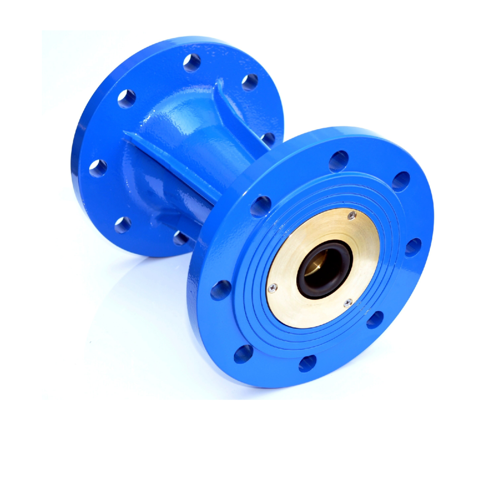

Ring-type modulating flow limiter for irrigation, without moving parts, with large ports for the passage of dirty or turbid water or with filiform suspended solids.
Ring-type modulating flow limiter for irrigation, without moving parts, with large ports for the passage of dirty water or with sediments or threadlike suspended solids. Maximum limiting accuracy with reduced pressure drop.
Automatic, gradual, and reversible flow rate modulating and limiting action, designed to prevent dangerous water hammers. Can be installed vertically, horizontally, or at an angle. Flanged or interflange versions, can be installed between flanges and recessed into the pipe. The robust construction with selected materials and precision machining guarantee maximum reliability with simple and quick maintenance.
16 Bar (PN16) maximum operating pressure. The maximum permissible pressure difference between upstream and downstream should not normally exceed 5 Bar. A downstream back pressure of not less than 1 Bar is also recommended. Operating temperatures between +10°C and +30°C. With their large full-flow outlet port and the absence of moving mechanical parts, modulating limiters are not subject to occlusions or seizure, even with very turbid irrigation water containing sand or foreign matter, including thread-like suspended solids.
A modulating flow limiter consists of an elastically deformable, differential-structure ring, held into a metal seat, extending downstream into a conical diffuser with high energy recovery capacity. At flow rates less than or equal to the specified nominal flow rate Qn (Q ≤ Qn), the limiter behaves like a “Venturi” nozzle with excellent hydrodynamic characteristics and therefore with minimal pressure drop (ΔH ≤ 2 m) (section a-b of the diagram).
However, when the outward flow rate tends to exceed the pre-set nominal value Qn, the localized loss increases, due to a complex hydrodynamic process, following a curve which is almost independent of the flow rate (section b-c of the diagram) and, as a result, the modulating limiter dissipates the entire excess of the differential load ΔH, preventing it from exceeding the value of 1.15 Qn. The modulating action is gradual and progressive, and therefore it does not cause water hammer.
• Size: DN 80÷250 simple type; DN 200 ÷ 600 multiple type
• PN 10 or 16
• Versions: flange/flange, interflange, recessed interflange
• Flow rate: 2 l/sec to 50 l/sec simple type; 60 l/sec to 500 l/sec multiple type
• High accuracy with low pressure drop at nominal flow rate
• Particularly wear-resistant
| Diameter | mm | 50 | 65 | 80 | 100 | 125 | 150 | 200 |
| inch | 2 | 2½ | 3 | 4 | 5 | 6 | 8 | |
| Qₙ | l/s | To be defined based on DN | ||||||
| Length | mm | 250 | ||||||
| Flange diameter | mm | 165 | 185 | 200 | 220 | 250 | 285 | 340 |
| Number of holes | n° | 4 | 4 | 8 | 8 | 8 | 8 | 12 |